 Networking & Communication
This week’s assignment was to design and build
a network between two processors. At first I thought this assignment was
simple, as it turns out, this week was very difficult. In total I made 6 boards
in an attempt to complete the assignment. This has been a positive thing
however, as I’ve built on my skills in EagleCad. I
asked my instructor for 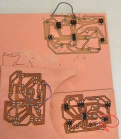 advice on
what would be a good thing to do and she suggested making 3 networking boards.
This was quite the challenge as there was much room for error as a beginner.
These boards had a lot of components that needed to be placed very
particularly. I used our Roland Modela to mill them
out, and a vinyl sticker stencil to lay out the solder. I learned that it is
best, when baking multiple boards, to not stack the PCB boards on top of one
another, it interrupts the
advice on
what would be a good thing to do and she suggested making 3 networking boards.
This was quite the challenge as there was much room for error as a beginner.
These boards had a lot of components that needed to be placed very
particularly. I used our Roland Modela to mill them
out, and a vinyl sticker stencil to lay out the solder. I learned that it is
best, when baking multiple boards, to not stack the PCB boards on top of one
another, it interrupts the 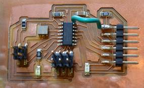 heat flow.
One of my 4 pronged jumpers popped of my board like popcorn while baking! Once
these board were complete, I had quite a few errors. I interpreted the
schematic incorrectly and had a few ground traces disconnected. Jumper wires
heat flow.
One of my 4 pronged jumpers popped of my board like popcorn while baking! Once
these board were complete, I had quite a few errors. I interpreted the
schematic incorrectly and had a few ground traces disconnected. Jumper wires 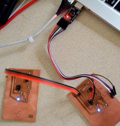 were used to
correct the problem, then it was on to programming. At first, we used the Atmel
ICE AVR programmer. This was tricky, as getting certain libraries to work was
not very straight forward. At one point my “master”
board was dropped and traces were broken. Also my “slave”
boards had mistakes too. I even started it all over
from scratch, this time hand soldering on the components. I scaled down my
ambitions and decided to try programming with Arduino, as this is how I’ve programmed
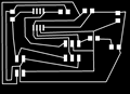
previous boards. Things went a lot smoother after that! This is my schematic. I used ATtiny 45s
on my simple circuit. These were
were used to
correct the problem, then it was on to programming. At first, we used the Atmel
ICE AVR programmer. This was tricky, as getting certain libraries to work was
not very straight forward. At one point my “master”
board was dropped and traces were broken. Also my “slave”
boards had mistakes too. I even started it all over
from scratch, this time hand soldering on the components. I scaled down my
ambitions and decided to try programming with Arduino, as this is how I’ve programmed
previous boards. Things went a lot smoother after that! This is my schematic. I used ATtiny 45s
on my simple circuit. These were 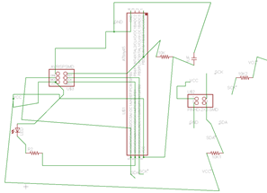 easier to
burn the bootloader onto, using our Fab ISPs we had made earlier. In Arduino, I
used some downloaded example sketches, TinyWireM
& TinyWireS to build the master and slave codes. It was fairly simple after that to figure
out what code I needed. I have a much
better understanding of programming and networking now!
easier to
burn the bootloader onto, using our Fab ISPs we had made earlier. In Arduino, I
used some downloaded example sketches, TinyWireM
& TinyWireS to build the master and slave codes. It was fairly simple after that to figure
out what code I needed. I have a much
better understanding of programming and networking now!